State Transition Testing Technique:
This technique falls under the Black Box testing techniques and the ISTQB syllabus excepts the tester to
1. understand State Transition diagrams and State tables
2. derive test cases from the State Transition diagrams and State Tables
3. Sequences – shortest, longest sequences
4. Null or Invalid transitions
5. Chow’s switch coverage
State-transition diagrams are very useful for describing the behaviour of a system and are part of the Software Design Document.
Any system where you get a different output for the same input, depending on what has happened before, is a finite state system. For example,if you request to withdraw $100 from a bank ATM, you may be given cash. Later when you make the same request you could be refused money (because your balance is insufficient). This later refusal is because the state of your bank account has changed from having sufficient funds to insufficient funds. And the transaction that caused your account to change its state was probably the earlier withdrawal.
A state transition model has four basic parts:(consider the ATM example)
The states that the software may occupy (funded/insufficient funds);
The transitions from one state to another (not all transitions are allowed);
The events that cause a transition (withdrawing money); –> Inputs
The actions that result from a transition (an error message, or being given your cash). –> Output
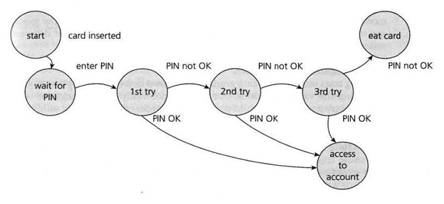
The figure shows an example of entering a Personal Identity Number (PIN) to a bank account. The states are shown as circles, the transitions as lines with arrows and the events as the text near the transitions.

P.S: the picture has been taken from the internet.
Not all events have an effect in all states. Where an event does not gave an effect on a given state, it is usually omitted , but it can shown as an arrow starting from the state and returning to the same state to indicate that no transition takes place; this is sometimes known as ‘null’ transition or an ‘invalid transition’.
eg. Invalid card entered
The state diagram shows seven states but only four possible events (Card inserted, Enter PIN, PIN OK and PIN not OK).
States: States can be numbered as S1, S2 or as alphabets A, B, C etc
S1:Start, S2:Wait for Pin, S3: 1st try, S4: 2nd Try, S5: 3rd Try, S6: access to account, S7: eat card
Events:
Event1:Card inserted, Event 2: enter Pin, Event 3: Pin OK, Event 4: Pin not OK
Actions : (not shown in the above example) could be : Messages on the screen – error or otherwise.
In deriving test cases, we may start with a typical scenario.
First test case here would be the normal situation, where the correct PIN is entered the first time. A second test (to visit every state) would be to enter an incorrect PIN each time, so that the system eats the card. A third test we can do where the PIN was incorrect the first time but OK the second time, and another test where the PIN was correct on the third try.
Or Test cases can be derived with sequences.
The smallest “sequence” is one transition at a time. The second smallest sequence is a sequence of 2 transitions in a row and so on.
Eg.:
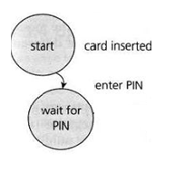
S1:Start –> Event 1(Insert card)—-> S2:Wait for Pin

You could also test a series of transitions through more than one state.
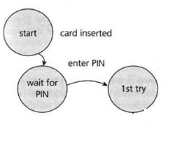
Eg for 1-switch (2 transitions): [double or a pair of sequential transitions]

The coverage element for state transition testing is measurable for different lengths of transition sequences for eg. all single transitions covered, all double covered, all triple covered etc. This is measured with Chow’s n-switch coverage where n= sequential transitions -1.
Chows 0-switch coverage is the percentage of all single transitions being executed in the test
i.e. (no of exercised single-transitions in sequence ) x 100
(total no. of single-transitions in a sequence)
Chows 1-switch coverage =(no of exercised two-transitions in sequence * 100) /(total no. of two-transitions in a sequence)
As is obvious, the State Transition diagram only shows the valid transitions between the states. (all transitions not shown are considered invalid). And this is a limitation of deriving test cases from a State Transition Diagram.
In order to see the total number of combinations of states and transitions, both valid and invalid, a State Table can be used.
A state table is a matrix showing the relationships between all states and events, and resulting states and outputs.
The state table lists all the states down one side of the table and all the events that cause transitions on the top (or vice versa).
Each cell represents a state-event pair. The content of each cell indicates which state the system will move into when the corresponding event occurs in that state. This will include possible negative or error events – events that are not expected to happen in certain states. These are the negative test conditions. We generate test cases by stepping through the ST. Each row/column intersection is a test case.
The State Table for the PIN example can be simplified as below:

Invalid or Null Transitions are represented as ‘-‘ in red in the table above.
Null or Invalid transitions are when the event has no effect on a state. We have put a ‘dash’ in the cells that should be impossible i.e. they represent invalid transitions from that state. Most of the invalid cells would be physically impossible in this case!
State transition testing is much used within the embedded software industry and technical automation in general. However, the technique is also suitable for modelling a business object having specific states or testing screen-dialogue flows (e.g.for internet applications or business scenarios).


